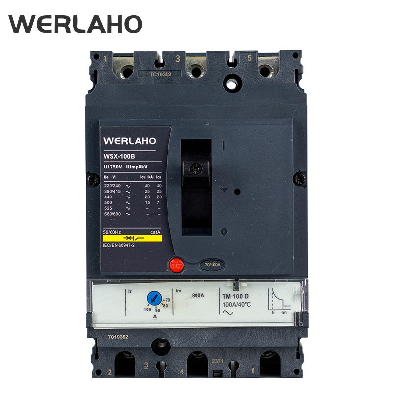

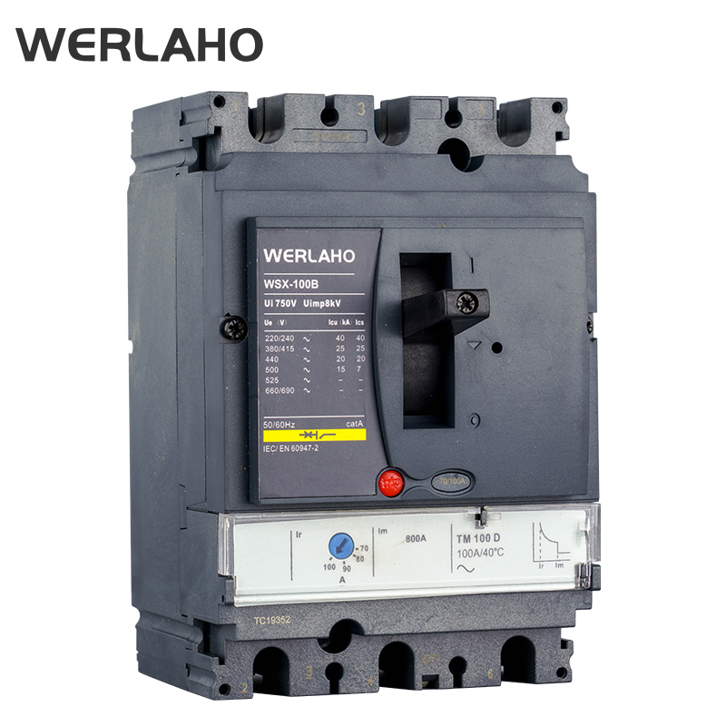
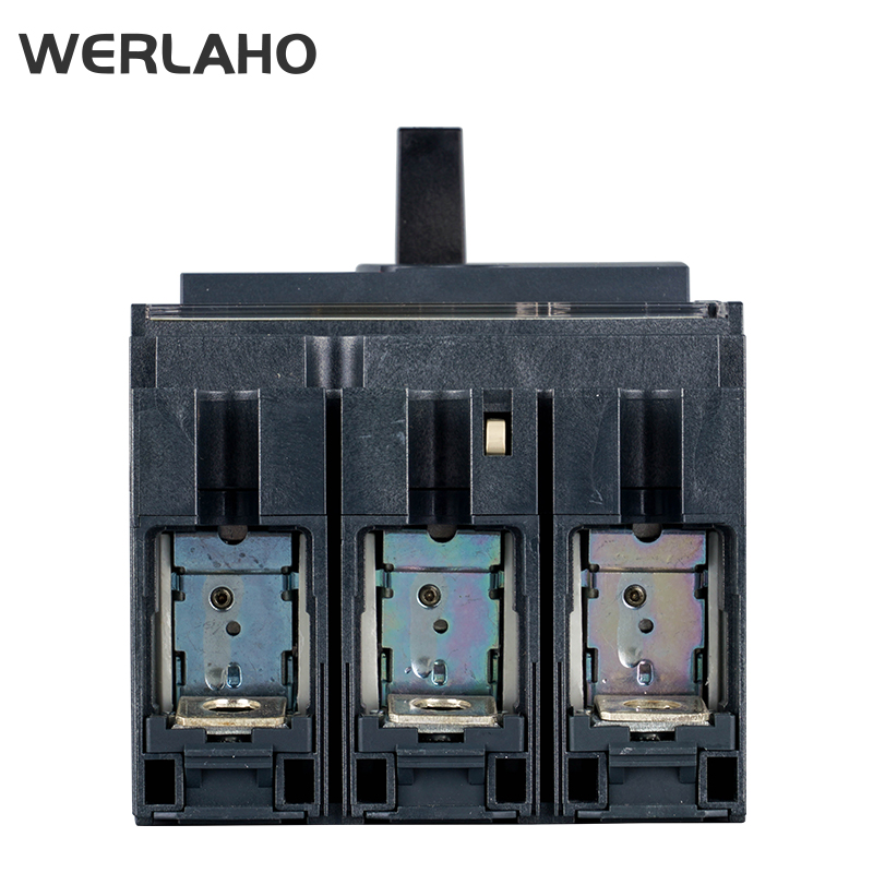
Application
WSX11 series MCCB is suitable for AC 50Hz/ 60Hz, rated operating voltage 690V and below, rated current 12.5A to 1600A distribution network, used to distribute electrical energy and protection lines and power supply equipment from overload, short circuit and undervoltage failure hazards. It can also be used as a non-frequent conversion of the line under normal conditions and in the infrequent start of the motor. WSX 11 MCCB complies to GB/T14048.2, IEC60947-2 standards.
Normal work and installation conditions
●The altitude of the installation site does not exceed 2000m.
●The WSX11 thermal magnetic type with temperature of the surrounding medium is-5 C~+40 C,and the average temperature of 24 h is not more than +35C.The relative humidity of the air at the installation site does not exceed 50%at a maximum temperature of +40C;at lower temperatures,there may be a higher relative humidity;the average minimum temperature of the wettest month does not exceed+25 C for the average of the month The maximum relative humidity is not more than 90%, and the condensation on the surface of the product due to temperature changes is considered.
●WSX11 intelligent type with temperature of the surrounding medium is-40C~+80C
●The product is used in non-explosive hazardous media,and the media does not have enough to corrode metals and destroy insulating gases and conductive dust.
●In places where there is rain protection and no water vapor.
●The installation category is Class lll.
●The pollution level is level 3.
●The basic installation of the circuit breaker is vertical or horizontal.
●The incoming line is either the up line or the down line.
●Circuit breakers can be divided into fixed and plug-in types.
Trip unit
| Thermal magnetic stripper(divided into two types according to protection type) | Distribution protection: TM | Intelligent stripper (divided into three kinds according to the function) | ordinary type: 250 frame:2.2., 630 frame:2.3. 800/1600 frame:2.0. |
| liquid crystal type:5.0A | |||
| Motor (single-magnetic) protection :MA. | with voltage detection type: 5.0E. module |
Note
Regular products only provide two-segment protection, if you need three protections pls tell us when making an order.( If there is any other particular requirements, pls also tell us directly)
Model Code

Technical data and performance (Adjustale type)
The basic parameters are shown as following table
| Frame Size | 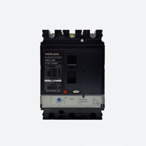 | 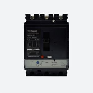 | 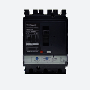 | ||||||||||
| Number of poles 3P/4P | |||||||||||||
| Model | WSX11-100 | WSX11-160 | WSX11-250 | ||||||||||
| Rated current(A)In | 12.5/16/20/25/32/40 50/63/80/100 | 100 | 16/20/25/32/40/50/63 80/100/125/160 | 160 | 100/160/180 200/225/250 | ||||||||
| Standard | IEC60947-2 | ||||||||||||
| Rated insulation voltage Ui(V) | 1000 | 1000 | 1000 | ||||||||||
| Rated impulse withstand voltage Uimp(kV) | 8 | 8 | 8 | ||||||||||
| Rated voltage Ue (V)50H-60Hz | AC415/500/690 | AC415/500/690 | AC415/500/690 | ||||||||||
| Flying arc Distance(mm) | 0 | 0 | 0 | ||||||||||
| Short circuit breaking capability level | L | M | H | S | L | M | H | S | L | M | H | S | |
| Rated limit Short circuit Breaking capacity Icu(kA) | AC415V | 50 | 85 | 100 | 150 | 50 | 85 | 100 | 150 | 50 | 85 | 100 | 150 |
| AC500V | 35 | 50 | 65 | 35 | 35 | 50 | 60 | 65 | 35 | 50 | 60 | 65 | |
| AC690V | 6 | 8 | 10 | 6 | 8 | 10 | 6 | 8 | 10 | ||||
| Rated running short Circuit Breaking capacity Ics(kA) | AC415V | 50 | 85 | 100 | 150 | 50 | 85 | 100 | 150 | 50 | 85 | 100 | 150 |
| AC500V | 35 | 50 | 60 | 65 | 35 | 50 | 60 | 65 | 35 | 50 | 60 | 65 | |
| AC690V | 6 | 8 | 10 | 6 | 8 | 10 | 6 | 8 | 10 | ||||
| Working with categories | A | A | A | ||||||||||
| Rated short time resistant currentICW (kA) (1s) | / | 3 | / | 3 | / | 3 | |||||||
| Type of Stripper | Thermal or single- magnetic | Intelligent type | Thermal or single- magnetic | Intelligent type | Thermal or single- magnetic | Intelligent type | |||||||
| Remaining Current protection | Additional Residual current protection module (See L6 remaining current module for speciǁc parameters) | ||||||||||||
| Electrical Life Test | AC415V | 10000 | 10000 | 8000 | 8000 | 8000 | 8000 | ||||||
| AC690V | 1500 | 1500 | 1500 | 1500 | 1500 | 1500 | |||||||
| Mechanical lifespan frequency | 20000 | 20000 | 20000 | 20000 | 20000 | 20000 | |||||||
| Dimensions | Wide(3P/4P) | 105/140 | 105/140 | 105/140 | |||||||||
| Long | 161 | 161 | 161 | ||||||||||
| High | 86 | 86 | 86 | ||||||||||
| Frame Size | 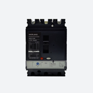 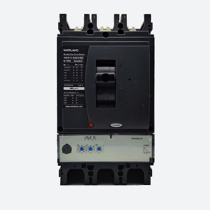 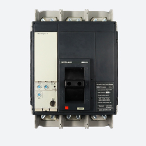 | ||||||||||
| Number of poles 3P/4P | |||||||||||
| Model | WSX11-400 | WSX11-630 | WSX11-1250/1600 | ||||||||
| Rated current(A)In | 250/315/350/400 | 400 | 400/500/600/630 | 630 | 800/1000/1250/1600 | ||||||
| Standard | IEC60947-2 | ||||||||||
| Rated insulation voltage Ui(V) | 1000 | 1000 | 1000 | ||||||||
| Rated impulse withstand voltage Uimp(kV) | 8 | 8 | 8 | ||||||||
| Rated voltage Ue (V)50H-60Hz | AC415/500/690 | AC415/500/690 | AC415/500/690 | ||||||||
| Flying arc Distance(mm) | 0 | 0 | 0 | ||||||||
| Short circuit breaking capability level | L | M | H | S | L | M | H | S | M | H | |
| Rated limit Short circuit Breaking capacity Icu(kA) | AC415V | 50 | 85 | 100 | 150 | 50 | 85 | 100 | 150 | 50 | 65 |
| AC500V | 35 | 50 | 60 | 65 | 35 | 50 | 60 | 65 | 35 | 45 | |
| AC690V | 10 | 15 | 20 | 10 | 15 | 20 | 20 | 30 | |||
| Rated running short Circuit Breaking capacity Ics(kA) | AC415V | 50 | 85 | 100 | 150 | 50 | 85 | 100 | 150 | 50 | 65 |
| AC500V | 35 | 50 | 60 | 65 | 35 | 50 | 60 | 65 | 35 | 45 | |
| AC690V | 10 | 15 | 20 | 10 | 15 | 20 | 20 | 30 | |||
| Working with categories | A | B | A | B | B | ||||||
| Rated short time resistant currentICW (kA) (1s) | / | 5 | / | 8 | / | 20 | |||||
| Type of Stripper | Thermal or single- magnetic | Intelligent type | Thermal or single- magnetic | Intelligent type | Intelligent type | ||||||
| Remaining Current protection | Additional Residual current protection module (See L6 remaining current module for speciǁc parameters) | ||||||||||
| Electrical Life Test | AC415V | 6000 | 6000 | 5000 | 5000 | 1500 | |||||
| AC690V | 1000 | 1000 | 1000 | 1000 | 1500 | 1000 | |||||
| Mechanical lifespan frequency | 10000 | 10000 | 10000 | 10000 | 10000 | 10000 | |||||
| Dimensions | Wide(3P/4P) | 140/185 | 140/185 | 210/280 | |||||||
| Long | 255 | 255 | 327 | ||||||||
| High | 110 | 110 | 147 | ||||||||
The overload delay and short-circuit transient protection action characteristics of the circuit breaker
| Serial NO. | Distribution breaker | Circumstance temperature | |||
| Test current(times) | Tripping time | Status | |||
| 1 | 1.05ln | 1h non-tripping (In s 63A) 2h non-tripping(In s 63A) | Initial | +40C+2℃ | |
| 2 | 1.3ln | 1h tripping(ln≤63A) 2h tripping (In>63A) | Following serial NO.1 | ||
| 3 | 10In+20% | 8In | >0.2s Tripping | Initial | Any sultable temperature |
| 4 | 12In | ≤0.2s Tripping | |||
| Serial NO. | Distribution breaker | Circumstance temperature | |||
| Test current(times) | Tripping time | Status | |||
| 1 | 1.05ln | non-tripping | Initial | +40C+2℃ | |
| 2 | 1.2ln | 2h tripping | Following serial NO.1 | ||
| 3 | 1.5ln | 4min tripping | The order 1 current reaches the thermal equilibrium and begins | ||
| 4 | 7.2In | 2~10s tripping | Initial | ||
| 5 | 12In+20% | 9.6ln | >0.2s tripping | Initial | |
| 6 | 14.4ln | ≤0.2 tripping | Any suitable temperature | ||
3.The current setting range of the circuit breaker
| Type | Overload long delay release current value adjustable range Ir(A) | Short-circuit short-delay trip unit current value adjustable range Isd(A) | Short-circuit instantaneous trip unit current value adjustable range li(A) | Remarks |
| WSX11-100 | 0.8~1In | - | 10In | Thermomagnetic (single adjustable) |
| WSX11-160 | 0.8~1In | - | 10In | |
| WSX11-250 | 0.8~1In | - | 10In | |
| WSX11-100 | 0.8~1In | - | 10In | |
| WSX11-160 | 0.8~1In | - | (5~10)ln | Thermomagnetic (double adjustable) |
| WSX11-250 | 0.8~1In | - | (5~10)ln | |
| WSX11-100 | 0.4~1In | (1.5~10)lr | 10In | Electronic (2.2) |
| WSX11-160 | 0.4~1In | (1.5~10)lr | 10In | |
| WSX11-250 | 0.4~1In | (1.5~10)lr | 10In | |
| WSX11-400 | 0.4~1In | (1.5~12)lr | (2~15)ln | Intelligent LCD display(5.0A) |
| WSX11-600 | 0.4~1In | (1.5~12)lr | (2~15)ln | |
| WSX11-400 | 0.4~1ln | (1.5~12)lr | (2~15)ln | |
| WSX11-400 | 0.7~1In | - | (5~10)ln | Thermomagnetic (double adjustable) |
| WSX11-600 | 0.7~1In | - | (5~10)ln | |
| WSX11-400 | 0.4~1In | (1.5~10)lr | 10In | Electronic(2.3) |
| WSX11-400 | 0.4~1ln | (2~10)lr | 10In | |
| WSX11-630 | 0.4~1In | (1.5~10)lr | 10In | |
| WSX11-630 | 0.4~1In | (2~10)lr | 10In | |
| WSX11-400 | 0.4~1In | (1.5~12)lr | (2~15)ln | Intelligent LCD display (5.0A) |
| WSX11-630 | 0.4~1ln | (1.5~12)lr | (2~15)ln | |
| WSX11-1250 | 0.4~1In | (1.5~10)Ir | 10In | Electronic (2.0) |
| WSX11-1600 | 0.4~1In | (1.5~10)lr | 10In | |
| WSX11-1250 | 0.4~1ln | (1.5~12)lr | (2~15)ln | Intelligent LCD display(5.0A) |
| WSX11-1600 | 0.4~1In | (1.5~12)lr | (2~15)ln |
Protection settings are shown as below table
| Type | Overload long delay setting current(IR) | Overload long delay (6.IN) Fix buckle time | Short-circuit shorter delay tuning current (ISD) | Short-circuit shorter delay setting time (TSD) | Short-circuit transient tuning current(li) | Grounding Protection setting current(IG) | Grounding Protection Setting time (TG) | Type of Stripper |
| WSX11-100 SDM6-160 WSX11-250 | (0.8~1)ln | - | - | - | - | - | - | Thermal magnetic type(single adjustable) |
| (0.4~1)ln | - | (1.5~10)lr | - | 10In | - | - | General Electronic (2.2) | |
| (0.4w1)ln | 1.5~24s | (1.5~12)lr | 0s ~0.4s | (2~15)ln | (30%~100%)ln | 0s~0.4s | LCD Intelligent Electronic (5.0A) | |
| (0.4w1)ln | (1.5~24)s | (1.5w12)lr | 0s ~0.4s | (2~15)ln | (30%~100%)ln | 0s~0.4s | Voltage measurement type(5.0E) | |
| WSX11-160 WSX11-250 | (0.8~1)ln | - | - | - | (5~10)ln | - | - | Thermal magnetic type (Dual adjustable) |
| WSX11-400 WSX11-630 | (0.8w1)ln | - | - | - | (5w10)ln | - | - | Thermal magnetic type(Dual adjustable) |
| (0.4~1)ln | - | (1.5~10)Ir | - | 10n | - | - | General Electronic (2.2) | |
| (0.4~1)ln | 1.5~24s | (1.5~12)Ir | 0s~0.4s | (2~15)ln | (30%~100%)ln | 0s~0.4s | LCD Intelligent Electronic (5.0A) | |
| (0.4~1)ln | 1.5~24s | (1.5~12)Ir | 0s~0.4s | (2~15)ln | (30%~100%)ln | 0s~0.4s | Voltage measurement type(5.0E) | |
| WSX11-1250 WSX11-1600 | (0.4~1)ln | - | (1.5~10)lr | - | 10In | - | - | General Electronic (2.2) |
| (0.4~1)ln | 0.5~24s | (1.5~12)lr | 0s~0.4s | (2~15)ln | (30%~100%)ln | 0s~0.4s | LCD Intelligent Electronic (5.0A) | |
| (0.4~1)ln | 0.5~24s | (1.5~12)lr | 0s~0.4s | (2~15)ln | (30%~100%)ln | 0s~0.4s | Voltage measurement type(5.0E) |
Intelligent voltage Measurement (5.0E)parameter measurement function is sh own as following
| Measurement values | Show | ||
| Instantaneous real and effective measurement values | |||
| Current(A) | Phase current and Neutral line current | 11,12,13,N | ■ |
| Average phase current | lavg=(I1+12+13)/3 | ■ | |
| The maximum value of phase current and neutral line current | Imax of I1,12,13,In | ■ | |
| Percentage of grounding faults | %lg | ■ | |
| Interphase Unbalanced Current value | %lavg | ■ | |
| Voltage(V) | Line Voltage | U12,U23.U31 | ■ |
| Line Voltage | V1N,V2N,V3N | ■ | |
| Average line voltage | Uavg=(U12+U23+U31)/3 | ■ | |
| Average line voltage | Vavg=(V1N+V2N+V3N)/3 | ■ | |
| Unbalanced line voltage,unbalanced phase voltage | %Uavg,%Vavg | ■ | |
| Phase sequence | 1-2-3,1-3-2 | ■ | |
| Frequency(Hz) | Phase sequence | F | ■ |
| Power | Active | P | ■ |
| Active | Q | ■ | |
| Seen in | S | ■ | |
| coso Power factors and measured | PF、COS, | ■ | |
| Maximum/Minimum value | |||
| Instantaneous real effective value measurement | Reset via Micrologic | ■ | |
| Reset via Micrologic | |||
| Electricity | Active (kWh),reactive (kVARh),visual (kVAh) | Total current absolute value mode or vector mode since the last reset ① | ■ |
| Requirements and maximum requirements | |||
| Current requirements | Phase current | The maximum amount required for the current value on the selected window since the last reset | ■ |
| Battery requirement | Active(kWh),reactive(kVARh),visual (kVAh) | The maximum amount required for the current value on the selected window since the last reset | ■ |
| Calculation window | Sliding,stationary,or communication synchronization mode | 1 minutes to compensate,adjustable range of 5-60 minutes② | □ |
| Power Quality | □ | ||
| Total Harmonic distortion rate (%) | Proportion of voltage value | Phase voltage THD,line voltage THD | ■ |
| Real effective value of current | Phase Current THD | ■ | |
| Measurement values | Show | |
| Cumulative record function | Total number of data clearing | ■ |
| Total trips | ■ | |
| Number of overload protection trips | ■ | |
| Number of overvoltage protection trips | ■ | |
| Number of manual trips | ■ | |
| Number of trips to zero protection | □ | |
| Test trips(remote,button) | ■ | |
| Short-circuit short delay trip times | ■ | |
| Short-term short instant trips | ■ | |
| Number of undervoltage protection trips | ■ | |
| Number of trips for phase loss protection | ■ | |
| Total accumulated operating time of circuit breaker | ■ | |
| Number of abnormal alarm occurrences/recoveries | ■ | |
| Number of protection function exits/resumes added | ■ | |
| New times of high voltage line loss/recovery | ■ | |
| Number of new gate status changes | ■ | |
| Self-test time additions | ■ | |
| Daily maximum and minimum records | On the day ..the maximum voltage of phase A and the time of occurrence on the 30th | ■ |
| On the day.the maximum voltage of phase B and the moment of its occurrence on the 30th | ■ | |
| On the day ..the maximum voltage of phase C and the moment when it occurred on the 30th | ■ | |
| On the day ..the three-phase current value at the moment when the maximum value of the A phase current occurred on the 30th day | ■ | |
| On the same day ..the 30th day of the maximum current value of the B-phase current and the three-phase current value | ■ | |
| On the day ..the time when the maximum value of the C-phase current occurred for the last 30 days and the three-phase current value | ■ | |
| On the day ..the minimum voltage of phase A on the 30th and the moment of occurrence | ■ | |
| On the day ..the minimum voltage of phase B and the moment of occurrence on the 30th | ■ | |
| On the day...the minimum voltage of phase C and the moment of occurrence on the 30th | ■ | |
| On the day ..the minimum current of phase A in the last 30 days and the moment of occurrence | ■ | |
| On the day...the minimum current of phase B and the moment of occurrence on the 30th | ■ | |
| On the day..the minimum current of phase C and the moment of occurrence on the 30th | ■ | |
| Record | 1 time...10 times circuit breaker self-test event record | ■ |
| Last..Last 10 Protection Action Event Records | ■ | |
| The last time...the last 10 times the protection function throws out | ■ | |
| Last...Last 10 gate change event records | ■ | |
| Last time ..Last 10 alarm event records | ■ | |
| The last...the last 10 high voltage loss recovery event records | ■ | |
| Maintenance functions | Contact wear history | ■ |
| RTC function | ■ | |
| Test function | ■ | |
| Electric operation control function | ■ | |
| Auxiliary/alarm detection function | ■ | |
| Human- computer interaction | LED indication | ■ |
| LCD Chinese display | ■ | |
| Button setting | ■ | |
| Communication function | Communication protocol of low voltage circuit breaker | ■ |
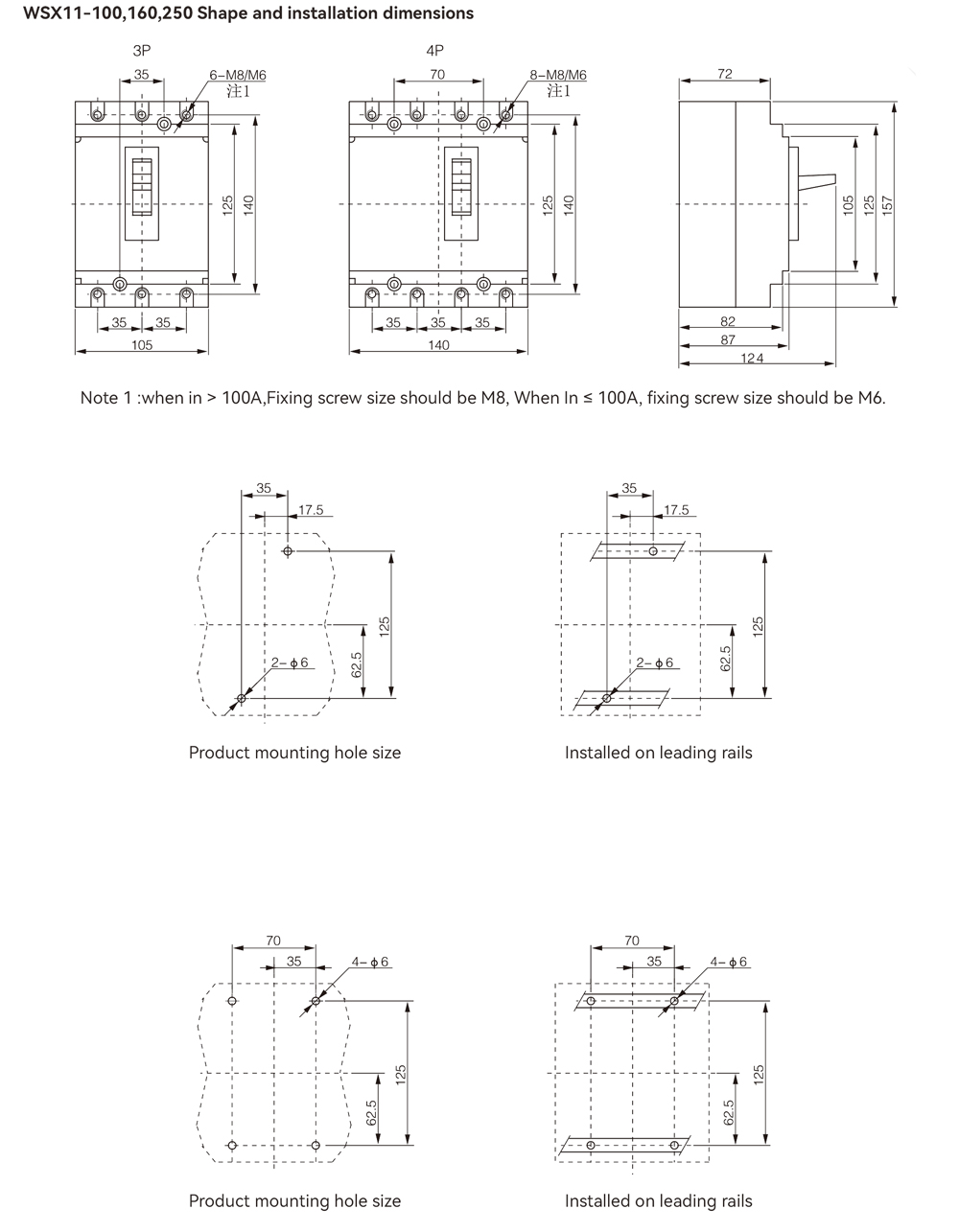
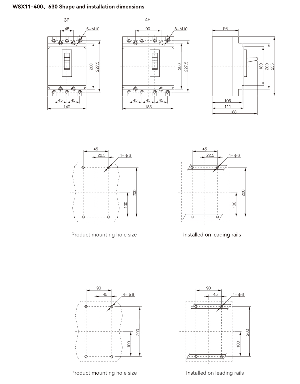
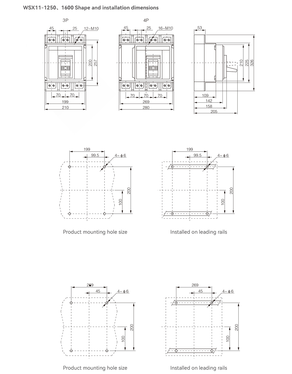
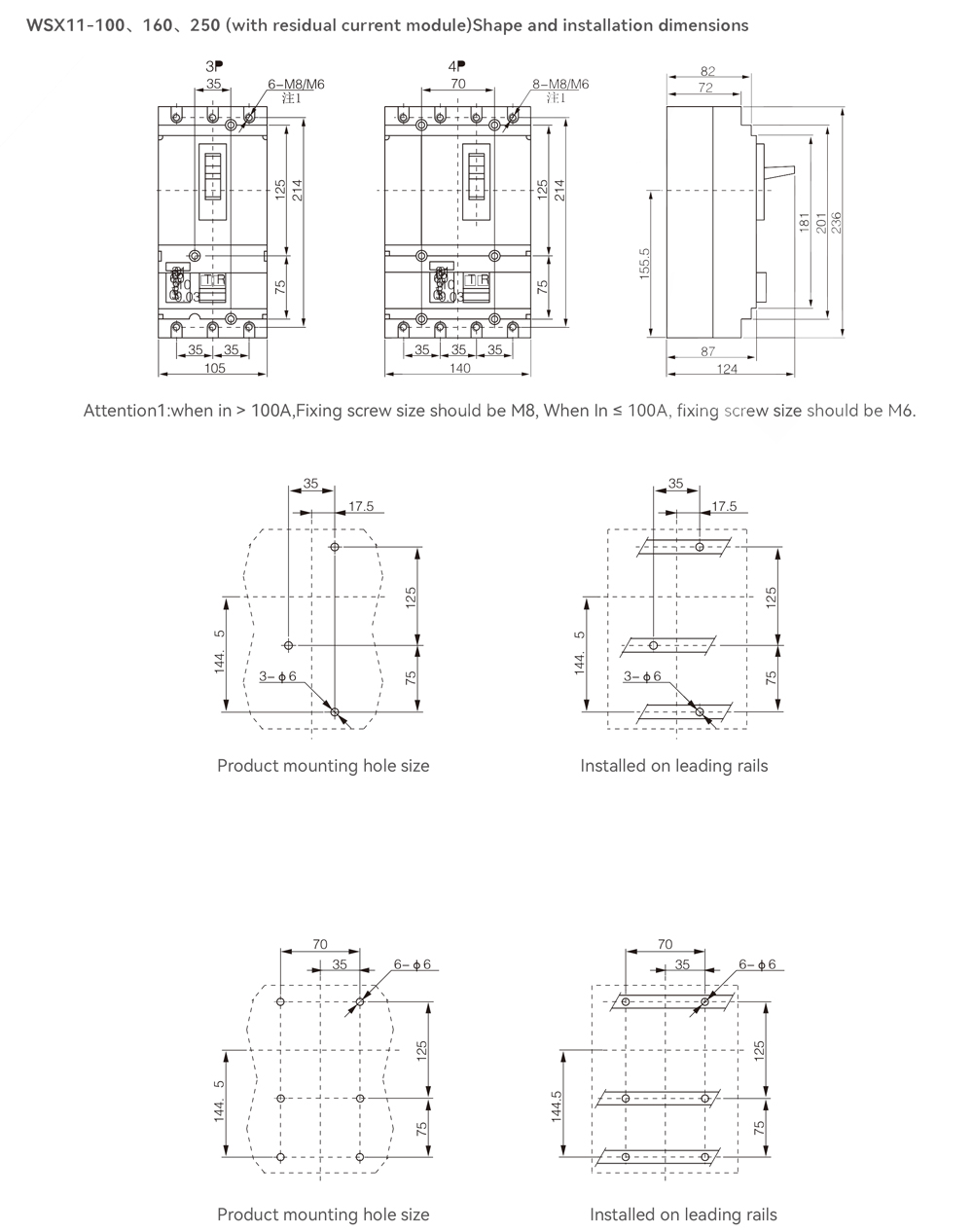
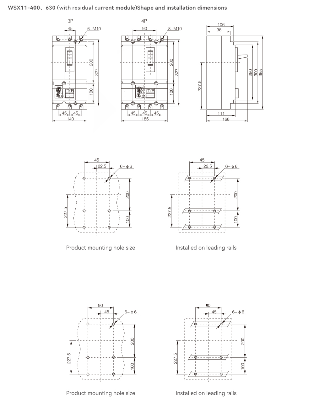
Shape and installation dimensions
